Back to Basics – Measuring Return Loss
The following is a re-post of a popular past blog post that explains the basics of return loss, why it’s an important measurement, and technologies for measuring return loss.
Fiber optic networks span a wide range of lengths. Intercity and transoceanic fiber optic telecommunications networks span thousands of kilometers. In aircrafts and ships, telecommunications systems have link lengths up to 500m. Data center networks have lengths on the order of meters. Finally fiber optic components have very short lengths on the centimeter and smaller scale.
Across all these applications, data needs to be sent with great fidelity from the source to the receiver. Any loss or reflection events along the way will contribute to a degradation of the signal. This blog post is intended to give an overview of potential sources of optical return loss (RL) and the importance of measuring it.
Definition of Return Loss
In technical terms, RL is the ratio of the light reflected back from a device under test, Pout, to the light launched into that device, Pin, usually expressed as a negative number in dB.
RL = 10 log10(Pout/Pin)
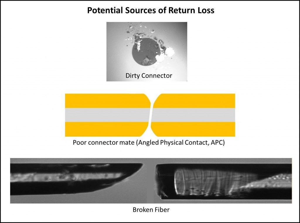
Sources of loss include reflections and scattering along the fiber network. A typical RL value for an Angled Physical Contact (APC) connector is about -55dB, while the RL from an open flat polish to air is typically about -14dB. High RL is a large concern in high bitrate digital or analog single mode systems and is also an indication of a potential failure point, or compromise, in any optical network.
What Does High Return Loss Indicate?
Dirty Connector
There are some very simple faults within an optical network that can cause high RL. A dirty connector is one such source. Even a tiny dust particle on a 5 micron single-mode core can end up blocking the optical signal, resulting in signal loss.
Broken Optical Fiber
A break in the optical fiber can also cause high RL. In some instances, it is possible for the optical fiber to have a break in it, but still be able to guide light through. In this case, a measurement of insertion loss (IL) across this fiber will result in a low IL. This disguises the extent of the problem where a direct RL measurement would immediately highlight it. In addition, a crack in a fiber can have both low IL and low RL and easily be missed as a problem in the system. However, a sensitive RL measurement will show a reflection peak where there should be none, indicating a crack in the fiber that will likely lead to failure.
Poorly Mated Connector
If a connector is not fully seated, the resulting air gap between connector end faces would result in high RL from that point. In this case, the IL may be low and the signal fidelity could still be good. However, this would be a source of concern as this loose connection is now a possible source of failure, as it could become misaligned or completely disconnected while in service.
Creates Multipath Interference and Degrades Signal
Multiple high reflection points within a network can lead to the optical effect known as multipath interference. This interference can easily lead to signal degradation, especially in high speed networks. In addition, many fiber optic transmission systems use lasers to transmit signals over optical fiber. High RL can cause undesirable feedback into the laser cavity which can also lead to signal degradation.
Methods for Measuring Return Loss
There are three established reflectometry techniques used for measuring RL as a function of location along an optical fiber assembly or network: optical time domain reflectometry (OTDR), optical low coherence reflectometry (OLCR) and optical frequency domain reflectometry (OFDR). The different methods have tradeoffs in range, resolution, speed, sensitivity and accuracy. Typically, the low coherence technique is used for sub-millimeter resolution measurements over a limited range (< 5 m). OTDR is typically used for long range (several kilometers) measurements with low spatial resolution.
OFDR by Luna
OFDR, the technology used in our OBR product line, is ideal for measurements from the component level to short networks (up to 2 km). OFDR produces measurements with spatial resolutions as fine as 10 microns over 30 m or a few mm over 2 km. This high spatial resolution measurement over intermediate lengths can provide significant advantages. For example, when an OBR is used to troubleshoot a network on an aircraft it is able to very precisely pinpoint the location of a fault, so that a technician knows which panel to open or on which side of a connector the fault was located. The sensitivity of OFDR also makes it possible to detect small RL events such as cracks that would be difficult to detect with other methods, but could lead to in-service failures.
Learn more about OBR high-resolution reflectometers.